How I Made My Caving Lamp
I finished making my caving lamp (in May 2008) and thought I
would record what I did as I went along. I would definitely
have appreciated finding a site with all the relevant details on
when I was planning the light. So I figured if I couldn't find
such a site, why not embrace my techno geekery even further and
write one myself! Then other people making a lamp
for the first time at least have a bit of a starting point! At
some point I'll also get round to putting links in to show where
I got the various bits and bobs from.
- Contents:
- Here's a list of what I ended up using to make the light, in no
particular order:
- An old Oldham headset
- Four 3.7V 2600mAh 18650 lithium ion cells for each
battery pack (I made two).
- Self amalgamating tape
- Electrical tape
- A lithium ion battery charger
- Powerpoles: 2 for each battery pack, 2 for the charger
and 2 for the headset and also a crimping tool.
- The following types of sticky stuff:
- Araldite
- Arctic Alumina Thermal Epoxy (heat conducting glue)
- Silicon sealant
- Some sort of semi flexbile waterproof plastic glue...
- Some wire
- 2 Cree XR-E R2 LEDS (at the time of writing these are
the brightest ones...I think)
- A bflex driver from TaskLED.
- Some silicon grease.
- A selection of clickable shut Lakeland Plastic boxes.
- A small length of bungee.
- Soldering gubbins: solder, iron, wire strippers,
a multimeter is useful.
- A Carclo lens (I chose an 8 degree one for my spot
beam)
- A piece of copper pipe.
- Some heat sink of some sort.
- Some conformal coating for protecting circuit boards.
- Some sort of power tool like a Dremel or a JCB or
something...
- A Mr Kipling Cherry Bakewell.
- A fair bit of patience.
This is just a bit about justifying my choice of batteries etc and working out expected run times and that sort of stuff.
Batteries
I chose Lithium Ion batteries because they seem to hold more energy per unit weight than NiMH or NiCad. The drawbacks are that they need looking after more: you can't run them until they are completely flat and you have to be careful charging them. But since I was intending to use a driver circuit with a cut-off voltage that I can choose and I was going to buy a special charger I figured these difficulties didn't actually matter. I decided that using 4 cells per battery pack was a good tradeoff between weight and amount of battery life. LEDs
At the time of writing the 'best' LED seemed to be the Cree R2 although it only seems to be available from Australia. At 1A each LED gives of something like 270 lumens which doesn't mean anything to me but is pretty bright when you try it! My main worry was heatsinking. My light sepcifications are very similar to the Scurion in which the whole headset acts as a heatsink. To get round this I decided to mount the LEDs on a copper plate and connect this to a heatsink running through to the outside of the lamp which the connects to the helmet mounting bracket. At 1A, I suspect this still won't be enough heatsinking but the driver circuit I'm using has a temperature sensor which lowers the current when it gets too hot so my LEDs are still protected. In addition I'd only be running at 1A for relatively short periods underground. The Driver Circuit
I knew nothing about these before making the lamp so here's a quick intro, as I understand it: - Batteries don't have a constant voltage - it gradually
drops. This means that the current through the LED will gradually
fall and it will get dimmer as the battery drains. This is annoying.
- A driver circuit gives out a constant current to the LED.
- There are two types: boost drivers are used when the voltage
of the battery pack is lower than the required voltage of the
LEDs. Buck drivers are used when the battery voltage is higher than
the required LED voltage. There are some that are both buck and
boost (useful as the voltage of the batteries drop below the
required voltage) but I'm told these are inefficient.
I decided to wire my cells in series to give about 15V. Two Cree R2 LEDs in series require about 8V. As the batteries discharge, since they are Lithium Ion, they need to stay above 8V anyway, so I had to choose a buck driver. I chose the bflex because: - It's a buck driver with the required voltage ranges.
- It has a low voltage sensor to protect my batteries.
- It has a temperature sensor to protect my LEDs.
- It's really clever: there's a chip in it and you connect it
to a switch to give you loads of control over your LED current etc.
Expected Run-Times
Disclaimer: these calculations might be wrong. Each battery pack contains 2.6Ah at 4*3.7 = 14.8V (although in fact when fully charged they are more like 4.2V per cell. so these estimates are conservative). Running at 1A the battery can deliver 14.8W for 2.6hours and therefore contains 38.5Wh of energy.
If I run my LEDs on full power, according to the datasheet they will want about 3.7V each = 7.4V. I make a conservative estimate that the driver is 85% efficient and so the LEDs will draw: 7.4*1/0.85=8.7W. This means they will run for about 4.5 hours.
The lowest current the driver can deliver is 40mA. At such a low current the LEDs only need about 2.5V each. This gives a runtime of about 163 hours or something stupid. But I've yet to test if they actually produce enough light to see by at this current!
A more sensible current for caving on might be 200mA. At this current the LEDs need about 3V. This gives a runtime of about 27 hours.
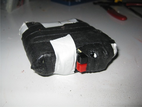 |
| A battery pack. |
I made the battery packs first. I soldered the 4 cells in series and connected the loose ends to powerpoles using a combination of crimping, soldering, glue and shouting. Red is positive, black is negative. I then glued the four cells together My previous light left the powerpoles dangling which put strain on the crimping everytime they were connected, so this time I glued the powerpoles down onto the tope of the battery pack. I added a bit of silicon sealant around the powerpoles and then wrapped the whole thing in vast swathes of self amalgamating tape to waterproof it.
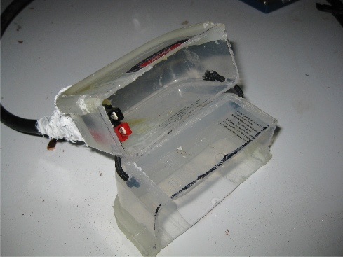 |
| The box. |
Next I made the box that the battery packs would sit in. This didn't need to be waterproof since the battery packs were. But it needs to protect them and also hold the powerpoles in such a way that they are not put under any strain. To make this I cut up a couple of Lakeland Plastic tupperware style boxes and glued them into the right shape using araldite. I drilled a hole in the bottom section through which the cable from the headet was threaded. This was glued using a slightly flexible plastic glue and also some silicon sealant. The powerpoles on the end of the cable were stuck to the side of the box using araldite and the top section was fixed to the bottom section using a bit of bungee. The battery packs now slot in until the powerpoles connect. It doesn't look pretty but it should definitely do the job.
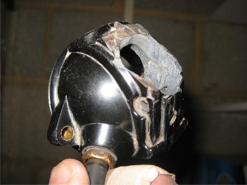 |
The mangled
headset. |
That was the easy bit done, now for the fiddly stuff. Firstly I cleaned out the headset. I unscrewed everything I could find on the inside and cleaned off any corrosion. I also took apart the switch and put some silicon grease on the inside of it to make it a bit more waterproof. I bent the contacts a little so that I can feel a bit more when the switch is on or off. Next I unscrewed the lamp bracket from the back of the headset and drilled a hole all the way through the back large enough to take my heatsink. This was ridiculously dusty work.
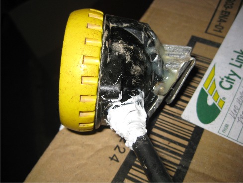 |
The
heatsink poking out the back. |
My heatsink consisted of a length of finned aluminium (with a star shaped cross section) about 2cm in diameter and 7-8cm long. I filed it down a bit and altered the shape of the end so that it would fit nicely. It was then threaded through the hole in the back of the headset such that when the lamp bracket thingy was screwed back on, the back of the heatsink sat flush against it. This join was glued using thermal epoxy so that the bracket can also act as a heatsink (as can the bit on the helmet ift here is good enough contact). The heatsink was then glued in place using araldite to create a strong waterproof seal at the back. The photo gives a bit an idea of what it looks like but what you can't see is that the heatsink extends all the way into the headset and there is a bit more exposed area of heat sink on the top that you also can't really see.
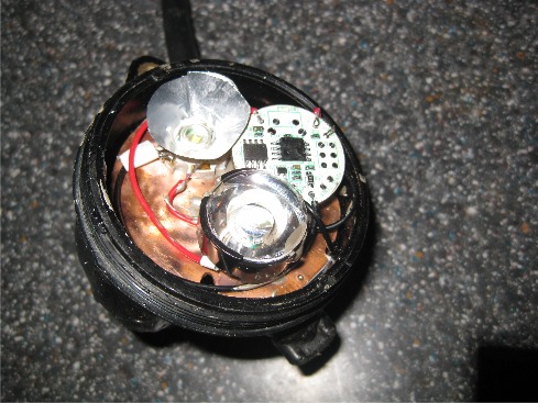 |
The front
of the headset. |
Now for the crucial bit: the soldering. I didn't want to get this wrong as I could potentially destroy both the LEDs and the driver circuit. I started off by cutting a piece of copper pipe, opening it out and hammering it flat to create a circular disc that fit into the front of the headset. The LEDs were glued onto the front of this (after I'd given it a bit of a polish) and everything was soldered together including the driver circuit. The relevant dangling wires were then conected into the appropriate part of the headset using solder tags. I order to protect the circuitry I tried to spray any exposed metal with conformal circuit coating stuff. I glued the copper disc into the front of the headset using thermal epoxy so that the copper disc sat flush against the aluminium heatsink. The circuit was also glued onto the disc using a small aluminium block fixed onto the temperature sensing chip with thermal epoxy. This means it would get a better idea of the LED temperature. One of the LEDs had a lens glued over it to create a spot beam. For the other LED I fashioned a reflector out of the foil casing for the cherry bakewell. The cherry bakewell was delicious. After this it was just a case of putting a bit of grease on the rubber o-ring and screwing the bezel back on. Job done! Update: The second trip my lamp went on (June 2008) was Providence Pot to Dow Cave via Dowbergill Passage. Unfortunately it took a severe disliking to the duck/sump. The headset flooded and frazzled the electrics. Luckily the LEDs survived. I think the leak was a combination of the heatsink and the switch. I got a replacement circuit and rebuilt the light with a bit of a design change. Firstly I stripped the headset right down, removing everything metal except the glued in heatsink. I replaced the switch with a waterproof push-button switch from RS, which was glued where the old switch used to be. Next I put the new circuit board behind the copper panel and filled the headset right up with thermally conductive potting compound, also from RS. This makes it extra waterproof and increases the heatsinking. I made a new reflector, this time out of a jam tart.
Update 2: Mid 2009. After over a year of fine service, one of my battery packs started playing up. I took it apart and found that two of the Li-Ion cells were dead whilst the other two still worked. I think that despite the circuit in the lamp, the 4 cells in the battery pack had become unbalanced. So for the new battery pack I ordered sets of 4 Li-Ion cells pre-soldered with a balancing PCB circuit thingy built in so that they can't become unbalanced and I don't have to be careful when charging or discharging them.